Cross-Member Spacing & Frame Torsion Resistance in Trailer Design
How cross-member spacing and design influence torsional stiffness, weight distribution, and structural durability in semi trailer chassis.
Chassis Engineering Structural Design
📅 Published on 2025-11-10 | ✍️ Semi Trailer News Engineering Desk
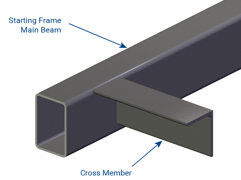
Image: Finite element model showing torsion distribution through cross-members on a 4-axle lowbed frame
🔹 The Role of Cross-Members
Cross-members are the **transverse beams** connecting the two main chassis beams of a trailer. They act like ribs in the skeleton — distributing loads, controlling twist, and maintaining the structural form of the platform. Spacing and design of these members determine how efficiently the frame resists **torsion** (twisting) and **bending**.
⚙ Spacing & Structural Behavior
Typical spacing ranges between 400 mm and 700 mm depending on trailer type and deck material. Closer spacing increases torsional stiffness but adds weight, while wider spacing saves weight at the cost of flexibility.
📊 General Design Guidelines
| Trailer Type | Cross-Member Spacing | Torsional Rigidity |
|---|---|---|
| Flatbed Steel Frame | 450 – 550 mm | High |
| Lowbed with Drop Deck | 600 – 700 mm | Medium |
| Container Chassis | 700 – 900 mm | Low–Medium |
| Aluminum Box Trailer | 350 – 450 mm | Very High |
🧱 Structural Mechanics Insight
When the trailer encounters uneven terrain, one side’s suspension rises while the other drops. This creates a twisting moment across the frame. Cross-members transfer that load from one side beam to the other, limiting the stress concentration on welds and suspension mounts.
The torsional rigidity (GJ/L) of the chassis increases proportionally with the number and section modulus of cross-members. However, excessive stiffness can lead to cracking if flexibility is completely eliminated — the frame must flex **within controlled limits**.
💡 Design Optimization
- Use closed-section (box or tubular) cross-members instead of open C-profiles for better torsional resistance.
- Alternate between heavy and light cross-members along the deck for weight efficiency.
- Weld cross-members symmetrically to minimize residual stress.
- For aluminum decks, use bolted joints to allow thermal expansion.
🏗 Industry Example
Manufacturers like Nooteboom employ a **variable cross-member grid** — denser spacing near gooseneck and suspension zones, wider spacing at mid-span. This design improves stress flow and weight efficiency without sacrificing torsional strength.
🧾 Maintenance & Inspection
- Inspect welds at cross-member ends every 20,000 km for fatigue cracks.
- Check for corrosion or paint loss near junctions — early sign of vibration fatigue.
- Avoid cutting or drilling near cross-members during aftermarket installations.
Conclusion:
Cross-member spacing defines how a trailer behaves under real-world loads.
Balanced spacing — neither too close nor too wide — ensures a structure that’s strong, durable, and responsive.
In trailer design, the key isn’t maximum rigidity, but **smartly distributed strength**.